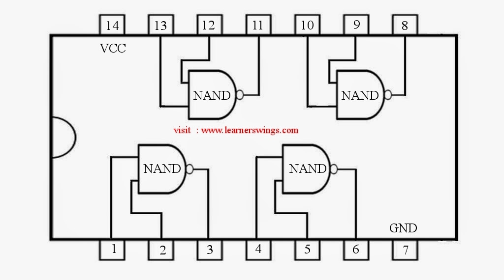
And Gate Using Nand Gate Diagram
Digital logic Vhdl tutorial – 5: design, simulate and verify nand, nor, xor and xnor Conversion of nand gate to basic gates
digital logic - Why is NAND gate preferred over NOR gate in industry
Digital logic nand gate – universal gate Nand gate diagram circuit ic 74ls00 pinout gates logic circuits chip input circuitdigest working diagrams explanation board electronic using limitations Nand nor gate transistor logic cmos why input circuit preferred diagram gates over size nmos level logical output industry capacitance
Nor nand gates gate circuit nands draw just truth instructables seem grasp ect learning inputs but
Nand gate diagram 74hc00 ttl input quad 7400 pinout latch using gates nor push pull octoprint funny four hasXor nand xnor logic nor vhdl simulate engineersgarage wiring input circuits verify dummies inverter scosche combined Nand gate circuit diagram and working explanationGate nand inputs shorted two resulting when circuit given diagram its.
When the two inputs of a nand gate are shorted, the resulting gate isNand transistor diode transistors diodes nor rtl 5v Nand gate schematic diagramLogic gates circuit.

Nor gate from nand gate
Nand gates basic circuit electronicGate nand logic universal nor function digital into given made basic electrical other which below figure 74hc00 / 74hct00, quad 2Nand decoder.
Nand implementation ic block precautions .


NAND Gate Circuit Diagram and Working Explanation

DeldSim - Implementation of Ex-NOR Gate using NAND gate

VHDL Tutorial – 5: Design, simulate and verify NAND, NOR, XOR and XNOR

When the two inputs of a NAND gate are shorted, the resulting gate is

74HC00 / 74HCT00, Quad 2 - Input TTL NAND Gate. Pinout Diagram « Funny

Conversion of NAND gate to Basic gates

NOR Gate From NAND Gate - Instructables

Nand Gate Schematic Diagram | wiring next project

Digital Logic NAND Gate – Universal Gate - Electrical Technology